To draw the mask layout of a circuit, two main items are necessary at the beginning:
1. Circuit schematic
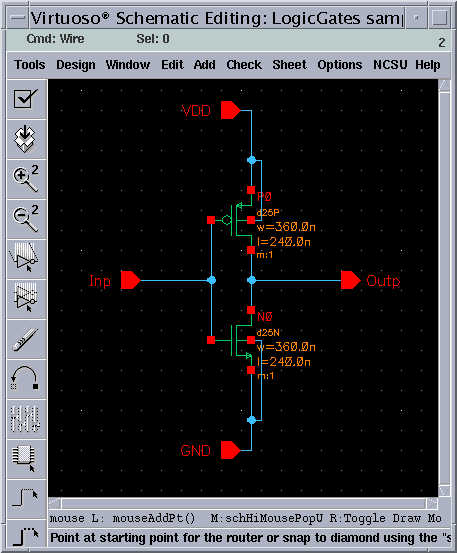
Any physical layout will actually correspond to a circuit schematic. It is important that the schematic of a functionally correct circuit is present and the layout is drawn according to the schematic (and not the other way around).
The schematic will the contain exact connection diagram and individual device properties. A example inverter schematic can be seen below. The schematic drawn in a way to resemble the final layout.
In this example the NMOS transistor and the PMOS transistor have identical dimensions W=0.36u and L=0.24u
2. Signal flow diagram
A layout can be drawn in a number of different ways. The most important factor determining the actual layout is the signal flow. The layout will almost in all cases be a part of a larger structure or the basic building element of an array of identical blocks.
In modern fabrication technologies, more than one physical layer can be used to transfer signals. For example with the fabrication technology used throughout this manual, a total of 4 layers (poly, Metal-1, Metal-2, Metal-3) can be used. The general flow of the signal connections as well as their layers need to be pre-determined. The following is an sample flow diagram used for the example layout:
In this flow diagram, it has been decided that all signals are on the same layer (blue, Metal-1) and that all signals will travel horizontally. Note that the signal flow diagram is just a concept that you can visualize for a particular circuit, or a simple sketch that you can scribble on the back of an envelope. The actual mask layout will roughly follow this concept.
We will assume, that you have logged on and started Cadence Design Tools, and that you already have created a design library for yourself.
1. From the Library Manager, choose File then New and then
Cellview
( File --> New --> Cellview )
2. Enter cellname and choose layout cellview
A dialog box will appear prompting you for the design library, cellname and cellview. Make sure that the library name corresponds to your design library i.e "LogicGates" , choose a name for your cell i.e "inverter" and choose Virtuoso as the design tool. The cellview will be selected as layout.
Two design windows will pop-up after you have entered the design name.
LSW
The Layer Selection Window (LSW), lets the user select different layers of the mask layout. Virtuoso will always use the layer selected in the LSW for editing. The LSW can also be used to determine which layers will be visible and which layers will be selectable. To select a layer, simply click on the desired layer within the LSW.
Virtuoso
Virtuoso is the main layout editor of Cadence design tools. There is a small button bar on the left side of the editor. Commonly used functions can be accessed by pressing these buttons. There is an information line at the top of the window. This information line, (from left to right) contains the X and Y coordinates of the cursor, number of selected objects, the traveled distance in X and Y, the total distance and the command currently in use. This information can be very handy while editing. At the bottom of the window, another line shows what function the mouse buttons have at any given moment. Note that these functions will change according to the command you are currently executing.
Most of the commands in Virtuoso will start a mode, the default mode is selection, as long as you do not choose a new mode you will remain in that mode. To quit from any mode and return to the default selection mode, the "ESC" key can be used.