Functional(Verilog) View of 2-Input Nand Gate
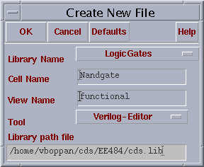
For the functional (verilog) view of the 2-Input nand gate, open a new cell view. In the field cell name, give the same name what has been given for the schematic of 2-Input nand gate. In The tool field, select verilog editor from the drop menu. Enter the view name as “functional”.
This will open a vi editor which will be as shown below.
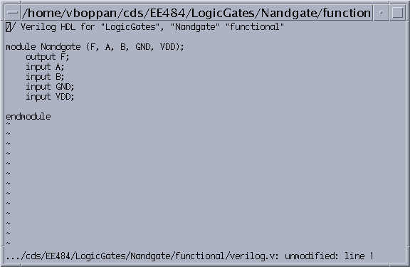
The verilog view which you see will have the
module name with the input and output in the port list adjacent to the module
definition. It will also have the input and outputs listed in the module. It
does not contain the logic of the 2-Input nand gate. We have to enter the
following lines after the input-output declaration.
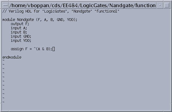
Assign F = ~( A & B); The
complete verilog description after this will be as shown below.
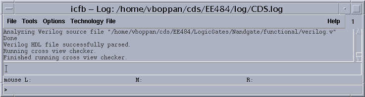
After this, to save and compile the verilog file, press shift :wq on the keyboard. This will save the file and also will compile the verilog code to find any syntax errors. The errors will be listed in the icfb window. The figure will be shown as below
You have written the functional (verilog) view for the 2 - Input nand Gate. Now we have the schematic view for the 3-input nor gate, extracted view for the inverter and functional ( verilog) view for the 2- Input nand gate, so we are ready to do run the simulation. Proceed to the next step