Back to Lab Exercises Next Step
Hierarchical Design
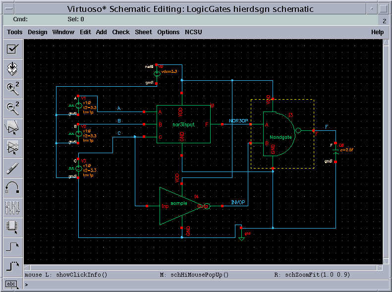
To do this exercise, you have to draw the schematic of the circuit as shown below. In this lab exercise, we will be simulating the circuit shown below.
The circuit contains three symbolic views of a
inverter, a 2-Input Nand gate and a 3-Input Nor gate. In lab#9, we have
simulated the extracted view from the layout and in lab#6 with the schematic
view. Like wise we can also use the verilog view for the circuit in the
simulation. For this particular exercise, we will be using the schematic view
for the 3-Input nor gate, the verilog view for the 2-Input nand gate and
extracted view for the inverter. However we can simulate the circuit
interchanging the views for the three symbolic views.
We already have the schematic for the 3-Input nor
gate, and the extracted view of the inverter. The views are shown below
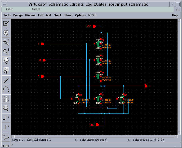
Schematic View of the 3-Input Nor
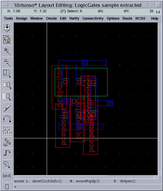
Extracted View of the Inverter
But we don’t have the functional (verilog) view
for the 2-Input nand gate, proceed to the next step