Step -2
Silicon
Ensemble -
Invoke Silicon Ensemble by typing the command "sedsm" from /home/<username>/cds/EE484/verilog.src in the console. This will open the window as shown below
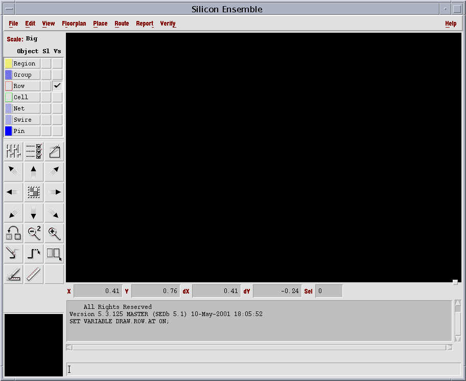
Figure -1
Click on "File" and select "Import" from the drop down menu and select "LEF" from the drop menu. The window shown in Figure-2 below will be opened. In Selection, the entry will be "/home/cdsadmin/vendors/VTVT/vtvtlib_lef/vtvtlib25.lef" and the Report file will be "importlef.rpt".
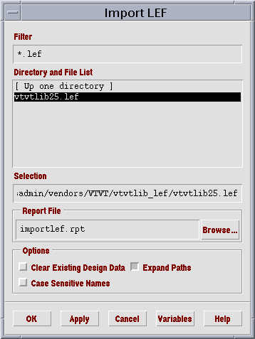
Figure - 2
Click on "OK".
Click on "File" and select "Import" from the drop down menu and select "DEF" from the drop menu. The window shown in Figure-3 below will be opened. The entry in Selection will be "/home/<username>/cds/<projectname>/verilog.src/cnt8bit.def"
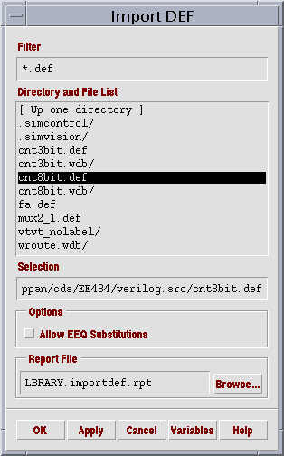
Figure - 3
Click on "OK".
Click on "Route" as shown in Figure - 1. Select "Plan Power" from the drop menu and the window will be opened as shown in Figure - 4
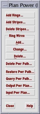
Figure - 4
Click on "Add Stripes". and a window will be opened. The entry in "Nets" must be "vdd" "vss". The Direction field can be vertical or horizontal and in this case select the direction as "Vertical" and the Layer will be "metal3" as the Place and route tool will use metal-1 and metal-2 for routing and interconnects. The entry in Width will be "0.96"(0.96um) and the Spacing will be "0.48"(0.48um). The entry in "Number of Sets" will be in this case one. We have to decide the number of sets appropriately depending on the number of modules present in the final layout. The window will be as shown below in Figure -5 after all the entries are entered.
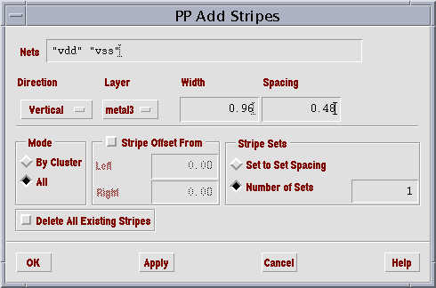
Figure - 5
Click on "OK".
Click on "Route" as shown in Figure -1 and select "WRoute" and select "Global and
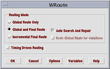
Figure - 6
Click on "OK".
After clicking "OK", the automatic place and route will take place and by clicking on the symbol in the left ( position : third row, 2nd column. The rows following the "Pin" entry), we will get the layout which will show the interconnect and the powerstripes. This is shown in Figure -7. The window will not show the internal view of the cells.
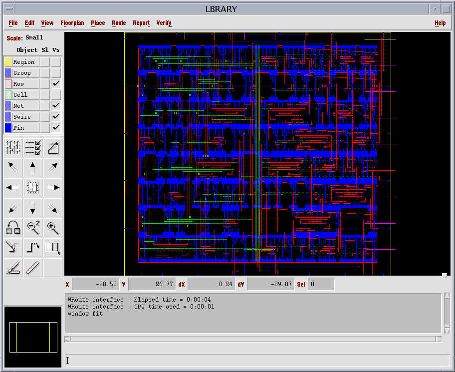
Figure - 7
To view the inner view of the cells, the layout has to be opened in Virtuoso Layout Editor. The output from the silicon ensemble has to be exported to a format that can be understood by Virtuoso Layout Editor.We have to export in to "GDSII" form. For this, click on "File" as shown in Figure -1, and click on "Export". The following window as shown in Figure - 8.
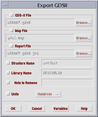
Figure - 8
By enabling "GDS-II File", type "cnt8bit.gds2". Enable "Map File" and the entry should be "/home/cdsadmin/vendors/VTVT/vtvtlib_lef/vtvt_se2df2.map". Enable "Report File" and the entry should be "cnt8bit.gds2.jnl". Enable "Structure Name" and the entry has to be "cnt8bit" and the library name will be "<ProjectName>". After all the entries are entered, the window will be shown below in Figure - 9.
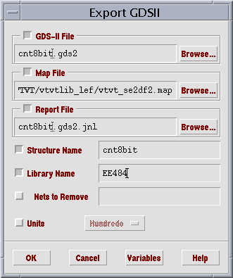
Figure - 9
Click on "OK" and exit Silicon Ensemble. Proceed to Step 3.