Step 5 : Simulating the Extracted Cell View
After a successful LVS you will have two main cell views for the same circuit.
The first one is the schematic, which is your initial (ideal) design, the
second is the extracted, that is based on the layout and in addition to the
basic circuit includes all the layout associated parasitic effects. Since both
of these views refer to the same circuit they can be interchanged.
In this example we are going to re-run the simulation example, but we will make the simulator to use the extracted cell view instead of the schematic cell view.
Make sure that you are in the test schematic, that you used to simulate your design earlier.
1. Create a new cell view in the "ece484LibTest" Library with the same cell name as the test schematic name for the inverter i.e. "invTest". Select the "Hierarchy Editor" in the "Tool" and that will automatically write down the view name for the Cell View which will be "config".
This will open the two windows as shown below.
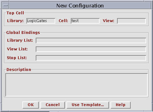
Popup Window-1
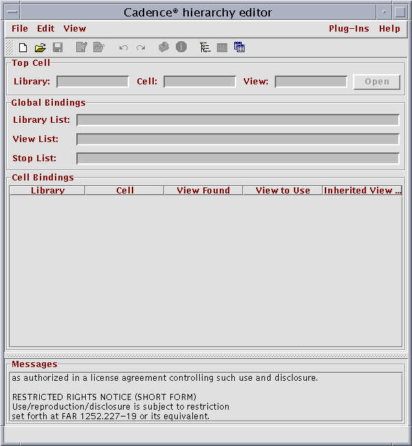
Popup Window - 2
The popup window-1 will be above the Popup Window-2.
The following entries have to be entered in the Popup Window -1
In the Entry "View" type in "schematic"
Click on "Use Template..." and a window will open which will be as shown below
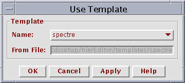
In This window, select the Name to be "spectre" from the pulldown menu and click on OK.
In the Popup Window-1, in "Library List", Enter the name of the Library where the schematic of the inverter resides i.e "ece484LibTest"
After all the above things are done, the Popup window will be as shown below
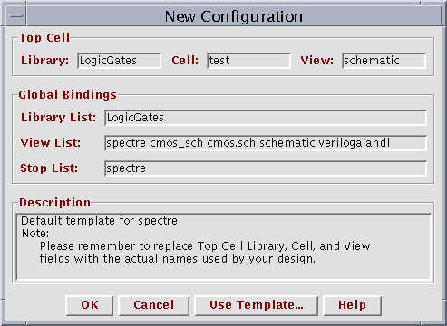
Click on "OK"
All the entries will be loaded in to the Popup Window -2 and it will be as shown below.
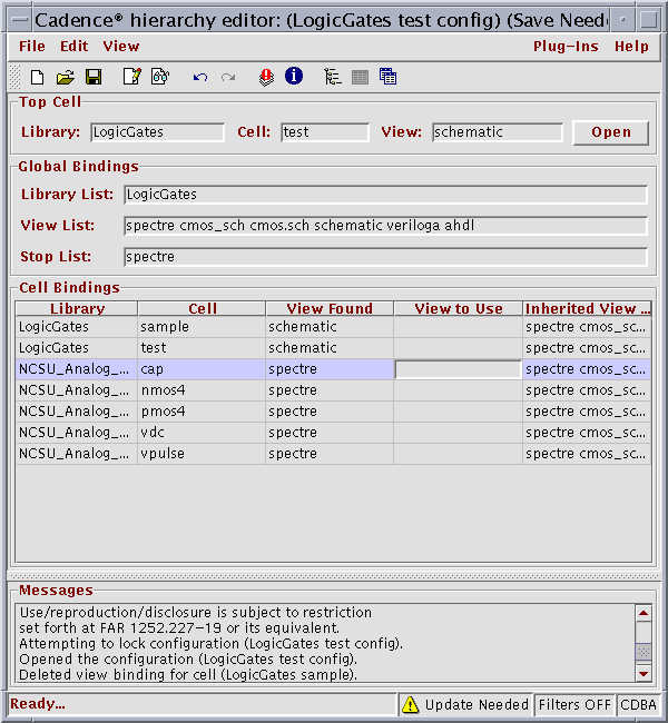
Click on "open" button which will be enabled. This will open the schematic of the "invTest". In the "View Found", it sees the schematic view. We have "extracted" view for the inverter. We had run the simulation for the inverter using the schematic view in Lab#2. In this lab we will be using the "extracted" view and run the simulation and see whether we get the operation of the inverter functionally right.
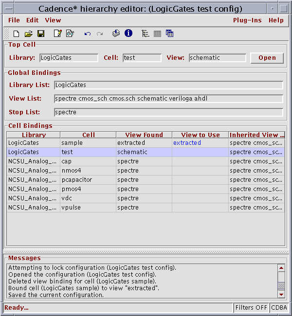
To do this, we type "extracted" in the column "View to Use" and click on 8th Icon (Red color) in the icon list which will update the config view. After doing this the Popup window-2 will be as shown below
Now run the simulation of the "Invtest". For this follow from step:7 in Simulation of Inverter in Lab#2.
The results must be show that the inverter is working functionally with the "extracted" view from the layout.