Step 1 : Extracting from the Layout
The mask layout only contains physical data. In fact it just contains
coordinates of rectangles drawn in different colors (layers). The extraction process
identifies the devices and generates a netlist
associated with the layout.
Make sure you have a layout window with a finished design ready. Make sure that the design does not contain any DRC errors.
1. From the Verify menu select the option Extract
( verify --> Extract )
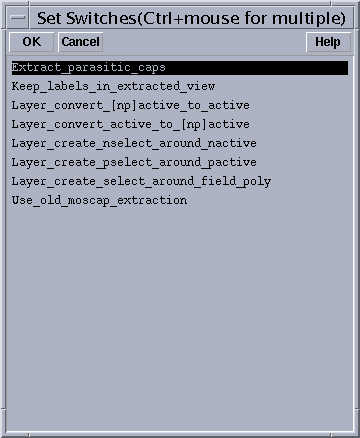
A new window with extraction options will appear. The default options will only extract ideal devices. This ideal case would result in a list much similar to the schematic. For a more accurate representation, however, we will have to take the parasitic effects into account. To enable the extraction of parasitic devices, a selection parameter called a switch has to be specified. You can type the switch into the designated box, or you can select it from a menu using the Set Switches option.
The switch specified in the example (above) to enable extracting the parasitic capacitances is called Extract_parasitic_caps.
Check the Command Interpreter Window (the main window when you start Cadence) for errors after extraction.
Following a successful extraction you will see a new cell view called extracted for your cell in the library manager. See the following section for accessing the extracted view.